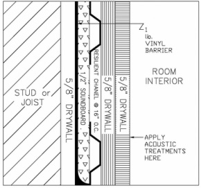
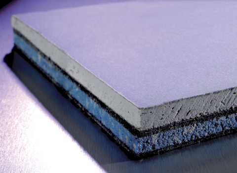
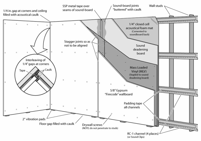
Seen below, is an existing technique, presented through a sourced drawing (http://soundproofing.org/images/wall_2d.jpg), of how a sound controlling wall is constructed and what is consists of in regard to materials and products used. However, this is an exploration into the possibilities of materials to be considered within my own project, as the following examples are to be layered and covered for aesthetic purposes, conflicting greatly with my polarised ideas of using these surfaces as a tactile element of the external wall. The most interesting feature of the image below, is that of the 'Sound Deadening Board', located centrally within the construct of the walls acoustically controlling performance. Seen within the image to the right and the section below, Sound Deadening Boards, or 'Sound Boards', are of a foam substance or material, rendering them rather lightweight and therefore not structurally viable in any sense. However, due to their light nature, these allow for an ease of installation as explored within the following brochure provided from the manufacturer of the JCW Silent Board product, explored in the right hand column. Above, presents a sectional drawing of the acoustic controlling arrangement presented in the image below. Although not representative of the techniques that I had wanted to explore within my own design, this creates an interesting precedent in which to perhaps develop as to reflect the attitudes and ideas that I had outlines within my brief, in regard to the spaces and atmospheres I had wanted to create. This would, I hope, allow for a greater realism within my technical design solutions, in the use or knowledge of current products as well as their composition or integration within similar precedents of design. | http://www.encon.co.uk/sites/default/files/products/images/silent_board_wall_0.jpgJCW SILENT BOARD Far from aesthetic elements, as well as from what would be required within my own construction, I feel that it would be important to explore the potential costing of such precedent products. Although difficult to find a precise price for the product from definitive manufactures and producers, I have found, within the hyperlinks below, that a suitable estimate to calculate from would be approximately £50-60 per panel, which can vary dependent on the size required. The figure provided is for a 27.5mm thick board, named as 'JCW Silent Board', seen within the links provided below. The board in question is 1.2m in both height and length (1.2m x 1.2m), in total 1.44m2 and has a total weight of 24.7kg; a fairly light material in comparison to the other structural elements that comprise conventional external walls. http://www.ebay.co.uk/itm/Wall-Sound-Proofing-Acoustic-Silent-Board-/160703401073Upon these measurements, I can calculate, below the required number of these panels needed as well as the financial costing of this, as to gain a perspective, financially, into this possible technique of creating an acoustically confined space, despite these products being utilised as to deter sound from escaping or bleeding from a space. In my external wall(s) that I am focusing on within this project, I would need approximately two boards, one above the other to obtain the optimal height of the space. | | SOUND DEADENING BOARDS
Soundboards are most commonly used within the construction of a wall, weather it be a partition or an external wall, to combat the sound transmission from one space to another. There are three principles that allow for this sound transmission to be reduced, the foremost being the increasing of the mass of the wall or partition, as to allow a greater distance for the sound to traverse through. This allows the transmission to become longer and with its extended travelling, it becomes weaker through the remaining two principles. These are the 'dampening' and the 'absorbing' of the sound, the latter of which has already been briefly explored within another precedent (see the Restaurant Acoustics Post). This is achieved through the use of materials, in particular the dampening aspect of the process, in restricting the sound waves from vibrating and through the uses of foam like materials and substances. These materials then compose the entire wall through different layers of varied substances, some harder, such as woods (the plywoods and drywalls seen within the provided images) as well as the acoustically orientated 'Sound Deadening Boards' explored in the right hand column. These layers then evoke the function of the absorbing principle, in creating more obstacles for the sound to travel through and become absorbed by before reaching the surrounding space (or atmosphere) that has been protected through these principles. | As a continuation of the calculations started above, my external walls are of 14.5m in length, with an average height of 2.4m (due to the incline that occurs towards the South Easterly space of the structure, an acoustic feature in itself). This would therefore result in the needing of a constant row of two boards being placed above each other over roughly 15m span.
15 ÷ 1.2 = 12.5 (13) One row for the span would be comprised of 13 1.2m x 1.2m boards.
13 x 2 = 26 I would then require a further 13 as to cover the area above the first row of boards, leaving the total for one external wall at 26 boards.
26 x 55 = £1,430 At an average estimated price (in using the
JCW Silent Board, above) of £55.00 I can calculate that the total cost of one external wall of the kitchen space, which would be £1,430.
|
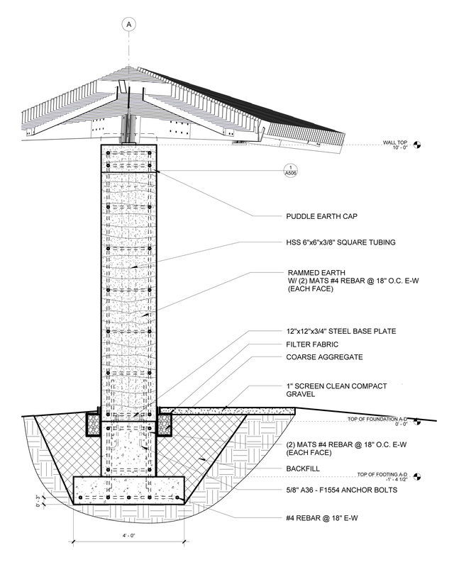
| In exploring the structural possibilities within Rammed Earth external walls, the use of steel reinforcement had become an important avenue in which to pursue. Although this would not be the fundamental structural basis upon which these external walls would depend on - in reference to the weight of the roof and the structure that would have to be applied to sustain such an element - this would be an interesting topic in which to begin to understand.
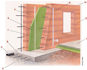
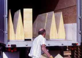
The use of steel reinforcement bars, or 'Rebars', is a practice used largely within concrete forms and structures, regarded as 'formwork' in allowing shapes to be created and then coated in a cast Insitu concrete substance. | | | | Similarly, this process can be used within Rammed Earth construction, although there are significant restrictions in terms of the shapes, spans and structures that can be created from this process. The image above outlines most clearly, how in actual fact these rebars are used within an external, Rammed Earth wall. Used as a formwork of sorts, the moist earth would then coat this skeleton, filled between two ply or steel casing sheets and then literally rammed and compacted together as to create a solid wall coating. This internal, skeletal reinforcement allows for less movement within the walls, as well as complementing the compact nature of the structure as a whole.
These technique can be seen applied to the structure presented within the sectional technical image (left), as a geometric pattern within the walls overall build up. These reinforcement bars, resemble a mesh inside of the earth, tied together to create a grid like sheet formwork for materials to be cast onto. As mentioned before, this is most popular as a process within cast insitu concrete construction and as a result of the material properties of both concrete and rammed earth, would both take significant periods of time to construct. This would be a result of the duration of drying periods. | | This form work, in terms of the rebars that are used within Rammed Earth walls and structures, also provide a degree of earthquake protection or support, perhaps evident by the abundance of these structures within earthquake prone countries or continents.
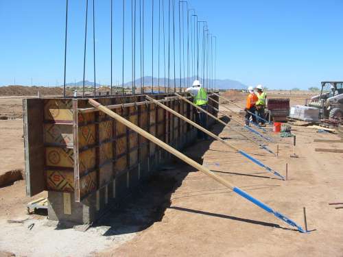
The image to the right presents the process of constructing a solid Rammed Earth wall most clearly, in presenting the formwork that is required to pour the moist earth between, as well as the vertical steel reinforcement that would have horizontal elements then tied to them before the next formwork and pouring is to commence. These are the steel bars that stretch high above the construction workers, pictured, which are most likely mapping the height of the structure that would be applied to this skeletal frame. | |
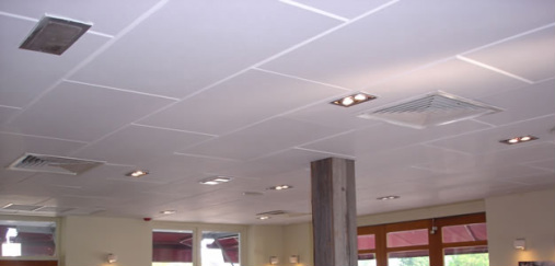
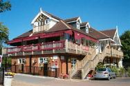
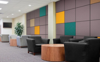
ON THE THAMES RESTAURANT (Precedent Study) The 'On the Thames' Restaurant, located in rural Buckinghamshire, within its design had issues with high noise levels as a result of the reverberations within the internal dining spaces. Due to its prestige as a restaurant, supported by the numerous reviews that remain of the establishment, even after its closure, these noise levels had apparently began to affect to some degrees, the functional, economically and perhaps social aspects of typology, in becoming lesser respected due to these acoustic issues. However, the acting management at the time had explored possibilities of how to implicate a greater comfort within an acoustic environment. Although relative to my ideas and concepts loosely, this precedent carries a more grounded, functional and economical response to a problem, as oppose to creating a deliberate atmosphere, as such is the case within my Pavilion project. In exploring solutions, the management had discovered 'Soundsorba', a company recommended by a customer involved within this manufacturer. Soundsorba, seen within the following hyperlink (http://www.soundsorba.com/), specialise in the production of sound insulation and most importantly, sound insulation panels. Seen within the image to the right, these panels are applied to internal spaces as to absorb reverberating sounds, creating a quieter atmosphere. | | Although the On the Thames Restaurant has officially been closed for over a year, the precedent remains relevant all the same. | | | | These panels (ECHOSORBA II) can also become either aesthetic features of the space, seen above in the waiting room image, or perhaps blend into the environment, such as can be seen directly above within the On the Thames Restaurant case study. | The image above, presents one of several typologies in which these panels can be applied, as well as the ways in which these can be implemented into a space, appearing almost artistic or decorative. This is a significant element of which this precedent had become relevant to my own ideas, as I had hoped to incorporate within these external walls, a tactile surface that doubled in both aesthetic and functional respects, absorbing reverberant noise and creating a visually and physically comfortable and soft space.
In referring back to the precedent case study, the On the Thames Restaurant had become most attracted to these panels through their effectiveness of acoustic absorption - which is approximately 86% sound absorbent - and the fact that these panels can be fitted by local labour, allowing them to be ergonomic as well as effective functionally. These panels, that possess these specifications and were used within this project, are the 'ECHOSORBA II' panels, seen within the image to the left. | | ECHOSORBA II PANELS
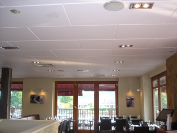
The ease of assembly within this product is largely derived from the processes that are required in order to apply such panels into the required space. Seen within the diagram to the right, the panels are attached adhesively to the surface of internal spaces, particularly the ceilings and the walls, as seen above in the On the Thames Restaurant ceiling (above image). As well as being considerably fast in its application, despite the drying times and the efforts to protect oneself from the adhesive sprays, produced by Echosorba Adhesive Spray cans specifically for this product and provided by 'Soundsorba', these are incredibly simple solutions whilst also providing resistance, or avoidance of other issues such as cold-bridging (of which will be addressed within my external wall structures later on within the development of the project). This application to the surfaces, rather than structural elements, also presents the avoiding of moisture damage and dampening, due to their existence as separate elements almost, appearing to 'clothe' the room.
| Despite the similarities within this case study, as well as the product itself and its compatibility with elements of my design, such as the way in which these panels are not to be applied to heated floor space above, due to the adhesive substances that bond them to the ceilings (or walls in the pavilion projects case) I feel that these are merely elements in which to consider within the development of this project and are not suitable for the atmospheres in which I wish to create. | However, particularly relevant in response to the inclusion of this system within the On the Thames Restaurant, was the effect that it had on the management of the time, in which they had claimed the acoustic works had been paid off for within weeks of competition, due to the 'full booking' of the restaurant and the sudden increase of customers that had began to enjoy the quieter environment. Although this is a functional respect, it presents a clear point in that even within this familiar space or atmosphere, the use of panels of this type (or others similar) creates a pleasant environment. To take a quote from the (http://www.soundsorba.com/restaurant.html ) webpage, would be that "Although my restaurant was fully booked last week, I could not hear the noise from the other half of the restaurant and got nervous in case all the customers had walked out. i was very relieved when I walked into the other half of the hall to find that the customers were eating and chatting very happily in the much quieter environment." | I feel that this was an interesting avenue in which to explore, particularly in assessing the capabilities of existing manufacturers and their products that exist and have been applied within working environments. However, I feel that I need to explore deeper into how I can translate the ideas outlined within my previous posts, with the atmospherics and attempted haptic and tactile spaces, into the use of existing products and precedents, despite the Echosorba II Panels becoming particularly relevant with their ergonomic implementation into an environment and its proven effectiveness. I feel that within my structure, these elements need to become more than panels and almost an extension of the structural elements of these external walls. This atmosphere or personality of the space that I want to create for the kitchen is best presented within the images of my conceptual kitchen model, pictured above left and above. |
| STEEL COLUMN POSITIONS
Although with having no definite dimensions at this early stage of the project, I felt that I could roughly depict where the columns would thread the structure together in plan. This drawing, produced before the construction of my final model (presented within the 'The Pavilion' hyperlink, above and the images below), then dictated the way in which my existing wall thicknesses were proposed upon my final model and how I therefore constructed it. This rough image, drawn originally at 1:50, proposes columns of roughly 2.5m high, in relation to the roofing strategy and thickness that would be placed above such a space.
The dimensions of columns that have been portrayed within the drawing (of which are a typical Universal Column form), are of a 20mm flange, with a length of its longest side at 220mm and the central element of 150mm. Although these are not accurate in the slightest in terms of representing the structure tectonically, these portrayed sufficient information within the model making process, seen within the following images. | | | | STEEL BEAM ISSUES
Within the design, the columns had been placed as strategically enough to encourage or infer the positioning of the steel beams that would then span the entire space as to support the garden space above. However, the columns are of unparalleled positions in several instances, there fore leading to necessary resolve within my structural strategy. This problem is also evident within the model images, to the left, although in having the central kitchen space as a structural element, may ease some of the tectonic issues of this design.
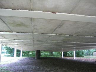
This could be within the inclusion of steel columns, or perhaps a separate grid, within the kitchen space, treating it technically as an individual element within the overall steel frame. There is already existing within this space, a central terminal or element, that is to harness all of the plumbing and electrical services through the bottom of the structure, and can be visible from underneath its raised floor. This took much inspiration from Ludwig Mies Van Der Rohe's Farnsworth House, that also addressed these issues of services in an almost identical way, with due to flood alleviation the structure had been raised (seen within the images). | | UNDERNEATH THE FARNSWORTH HOUSE
In order to prevent extensive flood damage from the nearby Fox River, Van Der Rohe, whilst designing Edith Farnsworth's 'weekend retreat', had raised the entire structure approximately five feet from the ground, passing all of the structural responsibilities onto the eight stilted steel columns that create the interior space. However, to create this almost floating illusion that had come with the raising of the structure, the services of the home, such as plumbing and electrical connections, all had to pass into the ground. This lead to the solution of creating one single output, seen within the image to the right, as a tube that conceals all of the vital and functional components. This was the solution that I had similarly taken within my own design, although the pavilion that I had designed is supported by a concrete piled foundation which then supports a concrete platform upon which everything is then built up from. This then allowed me to create a concrete pile that of a square shape to create a hollow space in order for services, of the kitchen area specifically, to then travel into the ground.
This was a process that I had then repeated within the other areas of the structure, of all the different rooms then having their own piled foundation which then has enough room within its centre to pass below. This can be seen slightly within the images provided of my final model, and of the plan drawn below. These concrete elements had taken large inspiration from the Farnsworth House example (pictured). | The images above and below are to represent similar ideas in terms of managing structurally, with the services of the structure whilst considering a solution to the steel beam and column issues. |
| WALL THICKNESSES
Although the model is only conceptual, it raised the issue wall thicknesses, of what I had been beginning to address within my first drafts of technical drawings. Initially, I had anticipated that structurally my walls would consist of Rammed Earth, in retaining an organic and somewhat vernacular attitude or personality of the pavilion in conversation with the natural aspects of the site. However, within the requiring of a second level, as well as outside space in adherence with the brief (both of the modules and my own), I had incorporated a roof garden space atop of the kitchen, due to its expanse.
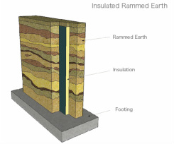
Unlike the models, the application of these wall thicknesses would be external, in travelling outwards rather than intervening within the internals spaces, allowing for less shifting of units inside. I had assumed that a 300mm external load bearing wall would have been sufficient for the structure, although when exploring the structural capabilities of Rammed Earth as a load bearing scheme, I had discovered and been instructed that it is only sufficient enough to support itself and perhaps a wooden framed structures, which would have been unsuitable for a roof garden of such a scale. However, through research, seen below, I had explored the possibility of steel framing which was then aesthetically 'wrapped' by the Earth. | | | Above and below present images used within my research as to explore the technicalities of Rammed Earth Construction, in beginning to look at it within section, assessing its composition of elements. | RAMMED EARTH
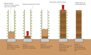
Although not structurally viable within my construction, Rammed Earth is a relatively simple and yet fascinating process, aesthetically and historically, creating an almost organic and definite 'earthly' colour and atmosphere, when applied to both internal or external walls. The diagram to the left, presents in simple enough terms, the fundamentals of Rammed Earth construction within a wall. With appropriate form work being placed, in the images case, a plywood frame, moist earth is then poured the space between and compressed. Although the image presents the use of machinery, in terms of expenses and historically, this compression can also be achieved by hand, although it presents a more onerous task physically.
In being an almost ancient technique, entire cities have been forged with such processes, although the perseverance of such structures rely on environmental factors such as particular climates, as well as human maintenance. Such a construction has also been proven to allow heat to leak slowly from an internal space, although as a stand alone insulator, it becomes fairly impractical without the inclusion of perhaps polystyrene, or another similar insulator as to retain this heat.
| | Perhaps most prominent within the southern hemisphere, or towards the Equator within much warmer and dryer climates, Rammed Earth historically, has proved itself as a fundamental constructional technique, which with the development and evolution of technology, has been adopted by the Western world and adapted to much wetter and cooler environments. However, one of the most impressive of all Rammed Earth structures is 'Ait Benhaddou', of Atlas, Morocco. Seen within the image to the right, Ait Benhaddou is an entire city, fortified behind a wall that holds six Kasbahs and approximately fifty houses within this territory. Impressive enough as it is today, the city is to have been conceived in the 11th century, when the first buildings (of rammed earth structure) were constructed, presenting its historical importance within construction.
This lasting stands as a testament to the structural potential of Rammed Earth as a material, although the almost sandy finish that has been created aesthetically appears regional, finishes can be applied within contemporary uses of Rammed Earth, seen within the images provided. It is this that I had hoped to apply to both the exterior and the interior aesthetic of these defining and load bearing walls within my Pavilion's structural design, in the form of block work perhaps, around the steel structural framework that I shall explore within the following. | |
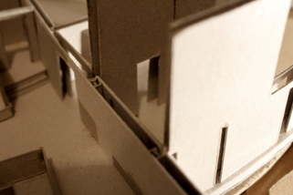
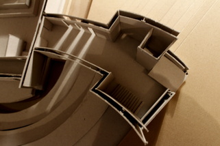
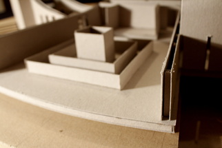
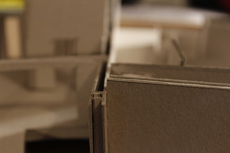
| For this current project, in exploring the tectonic elements of my pavilions design, I feel that it is necessary to describe, as best as my ability, the atmosphere that I had intended to create within such a space, therefore informing the technological materials and processes that will be explored over the course of this project.
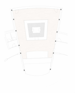
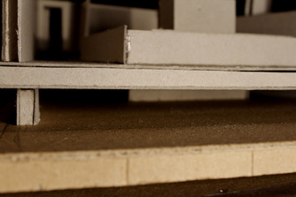
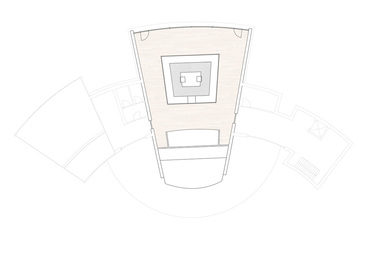
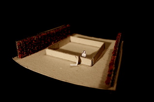
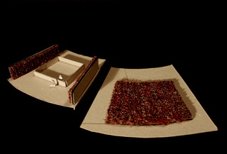
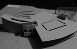
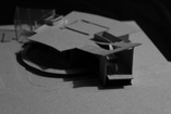
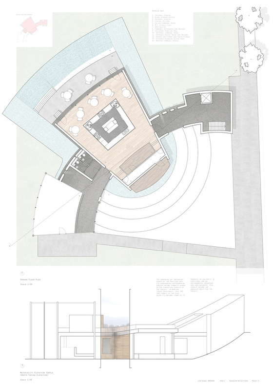
The diagram to the right, presents a highlighting of the kitchen space within the plan, as to portray its central importance, as well as a light and almost tonal presentation of its materiality, with the use of predominantly timber as a flooring element. The entire plan, even the enormous governing curved form of the structure had all been methodically revolved around and from this kitchen as a central 'hub'. | | | Although it may be a crude model in the uses of materials and its spatial accuracy (despite its scale of 1:100), the following images presents the tactile materials that I had wished to use within my kitchen space as to translate the intimacy of a 'home'. | | | ACOUSTICS
However, it is the acoustic element of this space that I had wanted to explore, particularly of the two external walls that define this internal and external shape. I had wanted to create an 'ear popping' experience once visitors had been exposed to the echoey tunnels of aromas and noises, acting as veins travelling into the heart of the structure, traversing into an almost nullified space, enhanced through the intimate ceiling heights, flooding of light and proposed tactile surfaces of both the walls, floors and ceilings. I had wanted to create a space filled with only the direct sounds of those who occupy it, as well as the noises of the foods, the chefs as well as the musical events that the space also accommodates with the provided staging areas. | | | A HOME
Both a physical and metaphorical driving influence within my design was the idea of a home, and the centralisation of both building and spaces to respond to this idea accordingly. This was heavily influenced from the idea of the kitchen acting as the heart of a home, particularly within British culture, and the exploring of this within a plan had began to govern the position of the pavilion within the Victoria Embankment as a whole. This had then allowed me to explore the social needs that I had wanted my structure to attend, most specifically within it beginning to act as a 'home' to the community, in the heart of the site. However, the most relevant idea from these studies that links directly into this project, was the atmosphere of a 'home' that I had wanted to recreate.
Within my kitchen space, which through my brief I had developed an understanding of an intimacy and enclosure, I had lowered the ceiling levels to 2.1m as to generate a more encapsulated, and almost 'cosy' space, which was largely dominated by the central kitchen island that was self contained, in providing an exhibition of foods. Although I had initially explored catering for around 15 persons, the space had become rather generous, resulting in the accommodation for larger quantities of visitors.
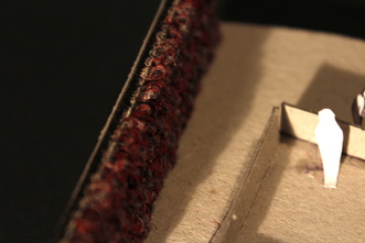
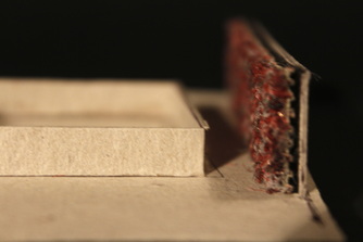
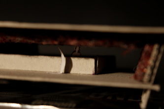
The focus within this kitchen space, will be the walls that dictate the shape of this space, and the exploration of their thickness and overall composition, structurally, aesthetically and functionally. The beginnings of such exploration can be seen within the image below, with the use of carpet invading the inhabitable space within the walls.
|
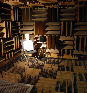
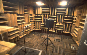
ANECHOIC CHAMBERWith the increasing technological advancements in regard to sound insulation and experimentation within design, the emergence of the Anechoic Chamber has been a particularly interesting invention. Currently used by manufacturers as to test their products noise emissions, prompting diverse sizes of these spaces to be produced as to provide enough useable room for a vast array of products, Anechoic chambers are a truly fascinating creation. This is primarily with their "99.99%" effectiveness of nullifying noise within its captured space. Although technically it is not completely silent, as 0.01% of sound can still infiltrate the space, these are undetectable to the human ear, therefore rendering these chambers absolutely silent, in what has been described as a 'sucking' of the sound from the space. These have had tremendous effects on those who have visited and experimented within these spaces, with the discovery emerging that if exposed to such a pure silence for an extended period of time, those who are experiencing the space begin to hallucinate, with themselves becoming the only producer of sound. Described as an 'ethereal' experience, in the detailed hearing of organs churning and functioning, as well as the sound of you own heartbeat becoming the only sound you are consciously aware of, these spaces appear playful with sound in an experimental, exploratory and functional respect, although also perhaps quite dangerous. Seen within the images, these spaces become possible with the use of the cleverly engineered Sound Absorption Wedges, of which are produced by 'ECKEL Noise Control Technologies' (http://www.eckel.ca/products/test-chambers/anechoic-chambers/anechoic-chamber-wedges.html). With this technology, sound becomes absolutely nullified within the space, sucking almost, whatever vibrations have been produced either through movement, voices or even internal organ processes as described above. However, these are extreme examples in relation to my own project, of which uses elements of the ideas portrayed within these precedents.
| |
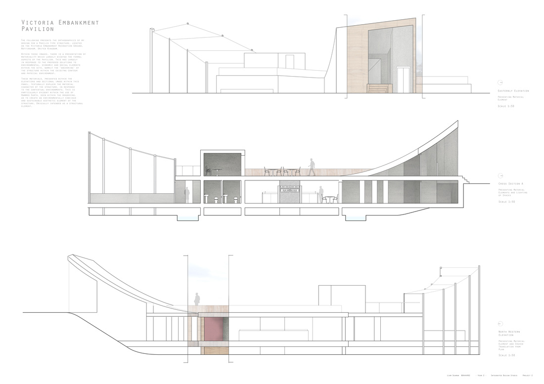
| I feel it important, before beginning to explore the technical aspects and engineering of the most haptic and atmospheric elements of my pavilion design and structure, that it would be beneficial to explore my current design through a large quantity of the work that I had submitted as part of my final critique on December 2nd, 2013. Although I am fairly content with the aesthetic and haptic natures and attitudes of the structure, as well as the symbolism that I had attempted to portray throughout the project in response to influencing contexts, I feel that there is significant room for development within both design and presentation respects. This is most evident within the distinct lack of information, or at least detailed information within my panels which is why I am hopeful that this process will allow for a greater depth in my explanation of the design, to justify its formal, atmospheric and symbolic qualities. | | SECTIONAL AND ELEVATION DRAWINGS - PRESENTING EXTERIOR AND INTERIOR MATERIALITY (Originally Drawn at 1:50) | SECTION AND ELEVATION DRAWINGS
The image above presents two of the elevation drawings that I had produced as to express materiality as well as how the structure would present itself to a passer by. Although these are fairly thin in terms of their actual presentation of information, particularly in regard to the material aspects and technical detail (most specifically of the section drawing, center) I feel that these are fairly effective in creating a depth within a two dimensional drawing.
All drawings presented on this panel are within the brief requirements of 1:50, as to express as much detail as possible and this was an area that I had failed to present sufficient information, although within the process of this project, will be closely analysing and strategising whilst looking technically at the the most interesting feature of the design as a whole, explained within the following texts. | GROUND AND SECOND FLOOR PLANS
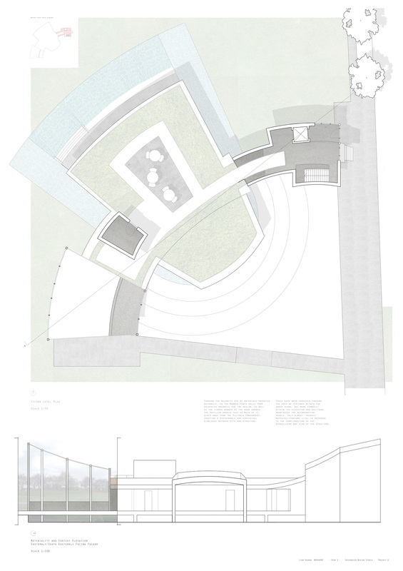
The following images below, are of both the Ground Floor and the Second Level access and Roofing Plans (of 1:50 scale) with the additional 1:100 scaled elevations, presenting the same vein of information shown within those above. The floor plans that are presented here, were most important as to show the interaction with the surrounding environmental contexts, particularly the height changes that have been hinted at within the sectional image. I feel that although these may appear fairly subtle within these images, rendered almost tonally, begin to express a more thorough understanding of the contoured personality of the site, creating a dialogue seen more obviously within the design itself and its use of these changes in height. | GROUND FLOOR ACCESS AND FUNCTIONS - FLOOR PLAN (Originally Drawn at 1:50) SECOND LEVEL ACCESS - FLOOR PLAN (Originally Drawn at 1:50)
|


 RSS Feed