| RAMMED EARTH WALL SECTION Taken from the extremely informative book 'Rammed Earth: Design and Construction Guidelines', the sectional image of an external Rammed Earth wall seen to the right, presents a basis from which I have been beginning to sketch upon. Through these images, in presenting both the roofing and the floor connections technically (although due to the scale, not in an enormous technical depth of detailing) I have been able to develop an understanding of conventional Rammed Earth structures tectonically. However, seen in my initial sketch below, I am still developing how I can incorporate the steel framed skeleton of the entire Pavilion, into a clear, concise and technically accurate graphic presentation (of which is explained further into this post). Although the scale is not indicated within the image to the right - as well as of the others within the series as part of the book - It does present measurements within the annotation and labelling of the design. One of the greatest difficulties that I had in producing my initial scaled sketch, seen below (originally drawn at a scale of 1:200) is that of the external Rammed Earth wall's connection within the concrete flooring, that itself does not sit within the ground, but above it due to the flood alleviation scheme that I had incorporated into my design, as a strategic response to the conditions of the site. | 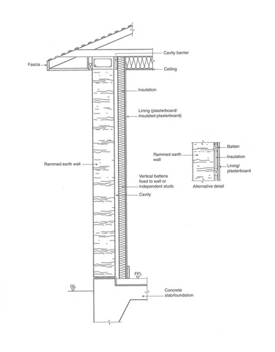 The image above is lacking in some detailing graphically, such as can be seen within the addition of a 'alternative detail' in which presents the ways in which these internal surfaces attach to the Rammed Earth wall. Depending upon the scale in which I am to choose for my final graphical presentation on the specified A1 panel, this may be necessary to include separate to the orthographic drawing. |
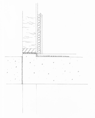 Even a drawing as inaccurate as that of the one above, has allowed me to assess in greater depth, the complexities of my structural design as well as beginning to think more rationally and technically whilst producing a sectional orthographic such as this. | Within the image to the left, my initial scaled sketch, is similar fundamentally to the image above, although there are few alterations, such as the inclusion of a 'up-stand', located at the base of the wall that separates the damp proof membrane from the Rammed Earth Material. An additional surface has also been added to the plasterboard that sits on the inner leaf of the cavity, as to represent the acoustic insulation panels, or surface, that will dress the walls of the internal kitchen space. However, relative to my own design, I feel that this is perhaps a way off of the correct tectonic strategy in order to connect a wall of this substance to the concrete 'slab' foundation that sits above an additional level of piles as to create this physical raising of the structure (much like the Farnsworth House, mentioned previously). This is also evident with my failure to include the piled foundation element within this sketch, although revised CAD drawings will be produced with the continued development of the technicalities of this element of my design. Simultaneous to this, I have began to construct models that present such a material as Rammed Earth, as accurately as possible. Below, is also a development on the graphic presentation of these details as a whole, as well as presenting much clearer my intentions within the realm of steel, and its use as a skeletal frame for the Rammed Earth to be poured around. |
| In beginning to explore graphical presentations of the development of my technical design and section, I felt it useful to begin diagramming and sketching (such as can be seen in the image to the right) potential ways/styles of key images for my final A1 panel. I feel that this describes the steel structure well within relation to my final model (see photos in 'The Pavilion' tab) as well as a small and yet informative section of the material build up of the wall. | 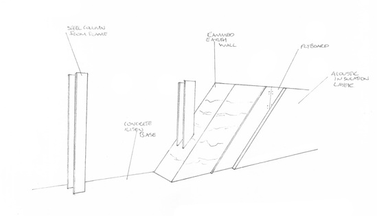 |
 RSS Feed