| THE INTERIOR FLOOR SYSTEM
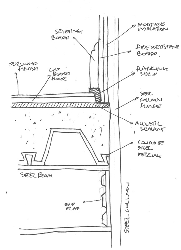
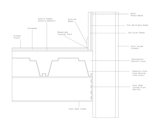
The sketch presented far right, presents in greater technical detail, the floor composition of the pavilion, from the steel beam that supports the structure, up until the visible flooring finish, as well as presenting its interaction with the wall system that, in the sketch is far less detailed.
This image will serve as a basis for development, up until my final 1:5 detail draft which will be presented at the end of this post.
IMPACTA RUBBER ACOUSTIC UNDERLAY
The first layer that I will be exploring in terms of practical and existing products, is that of the acoustic underlay that sits beneath the floors surface | finishes. Presented as a hatched plane in the drawing and labelled 'acoustic sealant', this layer seen as a product within the image below, allows for the insulation of noise, travelling either inwards or outwards from the structure.
Despite the underside of this flooring being hardcore - of which will be presented in the final sectional image - and therefore sound travelling from this direction into the space being of little issue, the escaping of noise into the ground is something that due to the atmospheric qualities of the interior space, I feel important to avoid.
In exploring possible practical solutions, I was first introduced to the 'Flanking' Strip, also presented within the sketch,
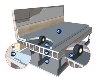
| '01', in the image above, presents the Rubber Acoustic Underlay within the constructional contexts of an 'acoustic floor system', as well as its connection and relationship with similar elements presented within the following post. | | although I shall explore that in more detail further within this post.
As a result of the materials that have been incorporated and utilised within the 'Impacta' Acoustic Underlay, primarily the fact that it is rubber, allows for a lack of increase in elevation, in regard to the floors invasion of space available within the internal space. This is particularly relevant as a result of the already unusually low ceilings within the pavilion, due | to its effects on the atmospheric goal that I have been aiming for.
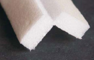
MONARFLOOR FLANKING STRIP
In order to prevent 'acoustic failure' or reducing the transmission of 'flanking noise/sound', 'Monarfloor' Flanking strips, comprised of a foam substance, are installed into the perimeter of a room.
The strategy is implemented within design, as to prevent the acoustic flooring, or 'acoustic system', from making
| | | contact with the structural walls, the points at which the acoustic floor systems can fail in allowing the transmission of sound.
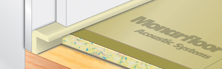
The foam threshold, of sorts, helps subtly retain the acoustics within a space, an extremely useful tool in the generating and retaining of the atmosphere that I have been developing towards within the Pavilion. This can be seen below, working with an 'acoustic floor system', that is similar to that within my | previous developments, although not representative of the flooring design presented in the sketch earlier.
Within the technical detail draft below, the element that represents a flanking strip, is modelled dimensionally, off of the 'Monarfloor' product, that being 6mm deep, by 35mm high and 25mm long. This was again to add a degree of realism within the design development, but also to explore the financial element of the chosen structure in detail. | | Although a foam product, the inclusion of a flanking strip within an acoustic system has been proven successful. The image above is not representative of the scale of the 'Monarfloor' product, of which the dimensions are 35mm x 25mm x 6mm. | | CHIPBOARD FLOOR
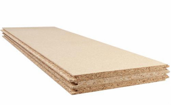
In providing suitable insulation for the floor composition within the pavilion, 'chipboard floors' boast a cheap, quick and cost efficient solution.
Within my own design, the Chipboard, of which the product seen in the image, right, is approximately 18mm in depth, provides moisture insulation from the ground in its moisture resistant nature. This accompanies the, to a degree, thermal capacity of the totally wooden product, whilst at the | same time, due to the products design - in being sold as panels - allows for a greater ease within installation through the tongue and groove system of each component. Installation however, is dependant on weather conditions, with the structure having to be completely weatherproofed before application.
This process also requires minimal tools, with the use of an 'application gun', bonding agent and 'weatherdek' tape being suitable enough for a high quality and functional finish. | | Upon the installation of such a material within the structure, the Chipboard is then layered on top of, with the preferred choice of material finish for the floor, whether this be underlay and then carpet, or in the case of this projects development, a hard, plywood finish.
The dimensions for the product presented above, are;
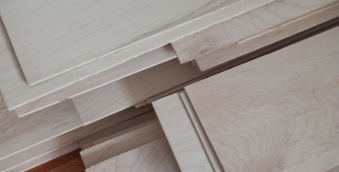
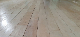
1220mm x 320mm x 18mm. | | Above, presents an image of the material in its purchasable state, and that of its utilised and applied state in a way to present how it is I would like to utilise such a product aesthetically within the spaces of the pavilion. I found it rather difficult to obtain financial information in regard to purchasing the desired 'plank' forms of plywood, instead being redirected towards panels for flooring surfaces. | | PLYWOOD FINISH
The final finish of the internal kitchen spaces flooring, will be that of a hard wood, or ply wood plank finish, polished and stained to the standard of that presented, left.
In being attached to the Chipboard layer that resides beneath it, the plywood surface should complete the floor systems composition, as well as sitting comfortably within the flanking strip that will support the rooms skirting board, above it (see detail sketch and final concept drawing below).
Despite having a pleasant aesthetic, the choice for such a conventional and perhaps common material as plywood, holds a deeper importance | within the identity of the space that I am trying to create and develop. In providing a material of convention, such as the polished wooden surface, I want the visitor or the user of the space to visually become adjusted to a recognisable surface, expecting the ordinary physical responses and stresses of a wooden floor once walked upon. However, I want this to played on and altered, by means of the acoustic insulation walls and floor systems, removing the bulk of the creaks and groans that erupt from a wooden floor surface. I hope that, although this may not tectonically be possible or presented well within my design, this attempt has been to a degree, successful. | | | FLOOR SYSTEM DETAIL
The image to the right presents the culmination of both the conceptual sketch seen at the start of this post, along with the research and development of specific materials and products that have been explored throughout.
Although there remain some areas that I am unsure of, most specifically in the arrangement of the wall surfaces and floor surfaces once they meet at the edges, or the perimeter of the space, I feel that this has proven to be a solid development of both my understanding of products, their roles within a flooring system and the general tectonic arrangement and composition of an 'acoustic' or perhaps regular flooring system. | Details, such as that of the outer leaf of the external wall and that of the insulation and similar elements below the steel beam, have been left from this image as so I can grasp an understanding of the immediate problem of the interior floor system, the remaining features having been presented within my sectional images, both final and the final (which will be presented upon my final graphic, A1 panels). |
|
 RSS Feed