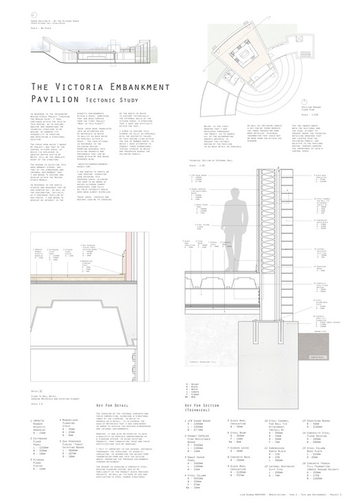
| THE INTERIOR FLOOR SYSTEM
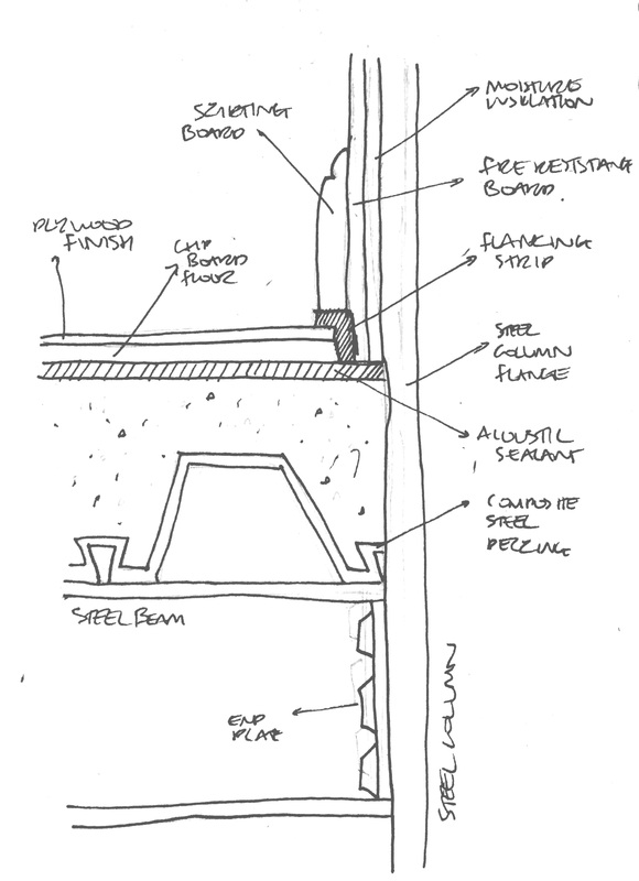
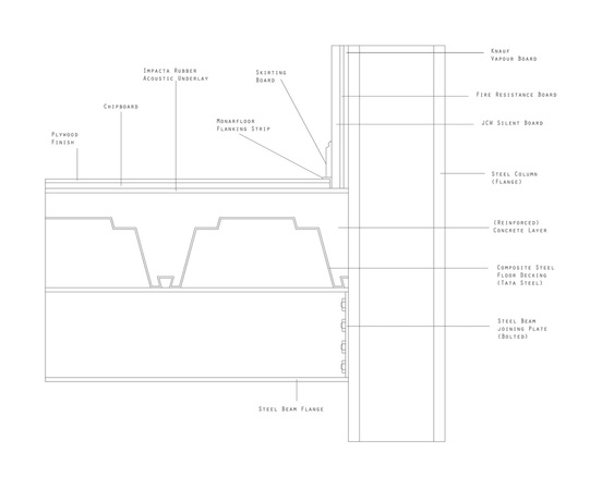
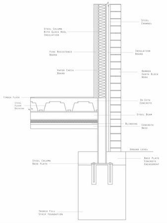
The sketch presented far right, presents in greater technical detail, the floor composition of the pavilion, from the steel beam that supports the structure, up until the visible flooring finish, as well as presenting its interaction with the wall system that, in the sketch is far less detailed.
This image will serve as a basis for development, up until my final 1:5 detail draft which will be presented at the end of this post.
IMPACTA RUBBER ACOUSTIC UNDERLAY
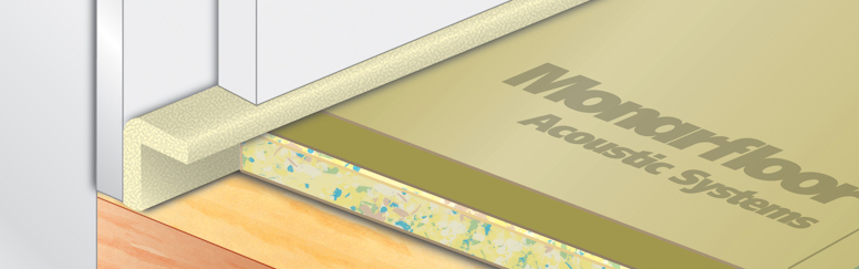
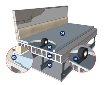
The first layer that I will be exploring in terms of practical and existing products, is that of the acoustic underlay that sits beneath the floors surface | finishes. Presented as a hatched plane in the drawing and labelled 'acoustic sealant', this layer seen as a product within the image below, allows for the insulation of noise, travelling either inwards or outwards from the structure.
Despite the underside of this flooring being hardcore - of which will be presented in the final sectional image - and therefore sound travelling from this direction into the space being of little issue, the escaping of noise into the ground is something that due to the atmospheric qualities of the interior space, I feel important to avoid.
In exploring possible practical solutions, I was first introduced to the 'Flanking' Strip, also presented within the sketch,
| '01', in the image above, presents the Rubber Acoustic Underlay within the constructional contexts of an 'acoustic floor system', as well as its connection and relationship with similar elements presented within the following post. | | although I shall explore that in more detail further within this post.
As a result of the materials that have been incorporated and utilised within the 'Impacta' Acoustic Underlay, primarily the fact that it is rubber, allows for a lack of increase in elevation, in regard to the floors invasion of space available within the internal space. This is particularly relevant as a result of the already unusually low ceilings within the pavilion, due | to its effects on the atmospheric goal that I have been aiming for.
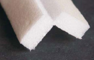
MONARFLOOR FLANKING STRIP
In order to prevent 'acoustic failure' or reducing the transmission of 'flanking noise/sound', 'Monarfloor' Flanking strips, comprised of a foam substance, are installed into the perimeter of a room.
The strategy is implemented within design, as to prevent the acoustic flooring, or 'acoustic system', from making
| | | contact with the structural walls, the points at which the acoustic floor systems can fail in allowing the transmission of sound.
The foam threshold, of sorts, helps subtly retain the acoustics within a space, an extremely useful tool in the generating and retaining of the atmosphere that I have been developing towards within the Pavilion. This can be seen below, working with an 'acoustic floor system', that is similar to that within my | previous developments, although not representative of the flooring design presented in the sketch earlier.
Within the technical detail draft below, the element that represents a flanking strip, is modelled dimensionally, off of the 'Monarfloor' product, that being 6mm deep, by 35mm high and 25mm long. This was again to add a degree of realism within the design development, but also to explore the financial element of the chosen structure in detail. | | Although a foam product, the inclusion of a flanking strip within an acoustic system has been proven successful. The image above is not representative of the scale of the 'Monarfloor' product, of which the dimensions are 35mm x 25mm x 6mm. | | CHIPBOARD FLOOR
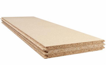
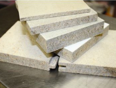
In providing suitable insulation for the floor composition within the pavilion, 'chipboard floors' boast a cheap, quick and cost efficient solution.
Within my own design, the Chipboard, of which the product seen in the image, right, is approximately 18mm in depth, provides moisture insulation from the ground in its moisture resistant nature. This accompanies the, to a degree, thermal capacity of the totally wooden product, whilst at the | same time, due to the products design - in being sold as panels - allows for a greater ease within installation through the tongue and groove system of each component. Installation however, is dependant on weather conditions, with the structure having to be completely weatherproofed before application.
This process also requires minimal tools, with the use of an 'application gun', bonding agent and 'weatherdek' tape being suitable enough for a high quality and functional finish. | | Upon the installation of such a material within the structure, the Chipboard is then layered on top of, with the preferred choice of material finish for the floor, whether this be underlay and then carpet, or in the case of this projects development, a hard, plywood finish.
The dimensions for the product presented above, are;
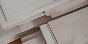
1220mm x 320mm x 18mm. | | Above, presents an image of the material in its purchasable state, and that of its utilised and applied state in a way to present how it is I would like to utilise such a product aesthetically within the spaces of the pavilion. I found it rather difficult to obtain financial information in regard to purchasing the desired 'plank' forms of plywood, instead being redirected towards panels for flooring surfaces. | | PLYWOOD FINISH
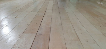
The final finish of the internal kitchen spaces flooring, will be that of a hard wood, or ply wood plank finish, polished and stained to the standard of that presented, left.
In being attached to the Chipboard layer that resides beneath it, the plywood surface should complete the floor systems composition, as well as sitting comfortably within the flanking strip that will support the rooms skirting board, above it (see detail sketch and final concept drawing below).
Despite having a pleasant aesthetic, the choice for such a conventional and perhaps common material as plywood, holds a deeper importance | within the identity of the space that I am trying to create and develop. In providing a material of convention, such as the polished wooden surface, I want the visitor or the user of the space to visually become adjusted to a recognisable surface, expecting the ordinary physical responses and stresses of a wooden floor once walked upon. However, I want this to played on and altered, by means of the acoustic insulation walls and floor systems, removing the bulk of the creaks and groans that erupt from a wooden floor surface. I hope that, although this may not tectonically be possible or presented well within my design, this attempt has been to a degree, successful. | | | FLOOR SYSTEM DETAIL
The image to the right presents the culmination of both the conceptual sketch seen at the start of this post, along with the research and development of specific materials and products that have been explored throughout.
Although there remain some areas that I am unsure of, most specifically in the arrangement of the wall surfaces and floor surfaces once they meet at the edges, or the perimeter of the space, I feel that this has proven to be a solid development of both my understanding of products, their roles within a flooring system and the general tectonic arrangement and composition of an 'acoustic' or perhaps regular flooring system. | Details, such as that of the outer leaf of the external wall and that of the insulation and similar elements below the steel beam, have been left from this image as so I can grasp an understanding of the immediate problem of the interior floor system, the remaining features having been presented within my sectional images, both final and the final (which will be presented upon my final graphic, A1 panels). |
| EDEN PROJECT
VISITORS CENTRE
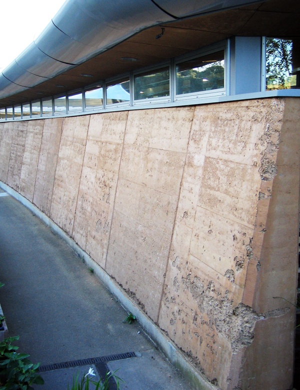
In order to address the issues of my external walls and the foundations they rest upon, I felt it important to begin to explore relevant precedent studies, that may shed light on potential solutions within the footing of the pavilions steel structure. The most relevant that was introduced to me, was that of the 'Eden Project', built in Cornwall, England, and completed in 2000.
Constructed by Grimshaw Architects, the Visitors Centre at the Eden Project holds the entire schemes key principles in its sustainable structure, environmental education facilities and its showcasing of low impact building, has been
| branded the 'Gateway' to the Eden Project.
In particular reference to the pavilions tectonic design, the external walls of this structure, which covers an approximately 15 hectare site, sits above a concrete plinth - seen also in the image below - as to raise the earth above ground level. Rammed Earth, or compressed earth blocks that can be seen within my own technical studies, cannot be used as foundations or structural elements below ground level, due to their material similarities with the soil and earth.
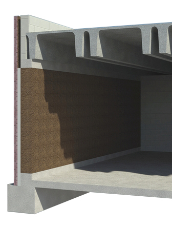
This concrete plinth can be seen in more detail, in the use of a sectional render image below, with the compressed | | | | Within following posts, I shall explore in more detail, the effects of such a small and yet vitally important elements implication within the pavilions external wall structure. This will include greater developed technical drawings, as well as a slightly more detailed insight into the technology and the roles that a concrete plinth can and will play within the construction. | | earth used as an internal aesthetic feature. This is the reverse almost, of the tectonic study that I have been developing, although it retains a similar arrangement at the footing of the wall and the relationship with the floor, are comprised of roughly similar elements. The most interesting aspect of these two examples however, is the way in which concrete has been added to the top of the foundation, forming a 'plinth', in which to separate the earth from ground level. As well as fundamental issues such as that of Rammed Earth sitting within the soil, being resolved though a fairly simple technique such as this, the problems of large volumes of moisture reaching or affecting the earth | in any way, appear to have been alleviated.
Within my own design, i feel it important to proceed in exploring this concept within my own design, in addressing the external leaf - the Rammed Earth block work - as a purely aesthetic element in acting as cladding, that sits above and attaches to a similar feature.
Although this will be presented in my 1:20 sectional image that is currently being developed in response to this short post, a 1:5 drawing will show greater detail in regard to application of such a feature. I would assume that my section (despite the absence of a roof), would take a similar form in regard to the image (left) and its footings. | |
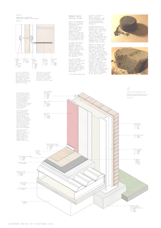
| MATERIALS
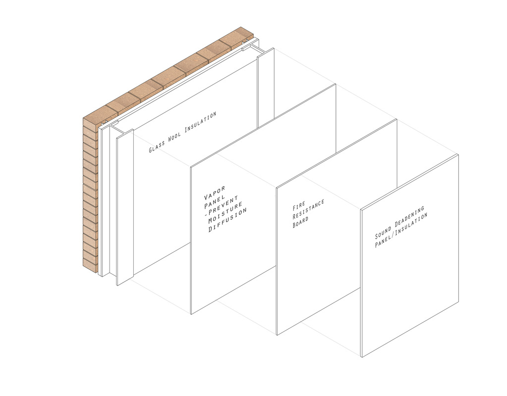
The image, presented far right, is that of a material breakdown, presenting the different surfaces that compose the entire external wall, from the inner leaf.
The first layer that attaches itself to the steel columns of the Pavilions overall structure, is that of a 'vapour' Panel that is explained in more detail below as a product. The reasons for such a material to be included within | the pavilions composition, is to stop moisture fro diffusing through the external leaf, affecting the materials, temperature and general atmosphere of the interior space.
The following layer, of which attaches to the vapour board behind it, also can attach to the steel frame and is the 'Fire Resistance Board' - again explained in more detail below. This is to withstand fire for a specified amount of time, found with the product research below. | | The Sound Deadening or Insulation Board has been explored and researched within previous posts ('Sound Control Walls') - See for Reference. | | | | KNAUF VAPOUR PANEL
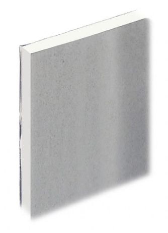
As introduced above, the first layer that I have applied to the inner leaf of the envelope, is that of a moisture resistance or 'vapour check' board. A traditional plasterboard element, is layered with a 'metalled' "Polyester Aluminium Foil", that is laminated onto the back of the original product.
The introduction of such a material, allows for a significantly limiting, or reduction, in the volume of moisture that can
| diffuse through the layer and begin to affect and damage the accompanying materials and surfaces of the external envelope, as well as other interior fabrics or materials. In having no distinct graphic identity, seen within the diagram above, as well as the image provided (left), I have presented this product as a vertical plane, similarly to the others of the walls composition, although the dimensions have been kept strictly accurate to the specifications outlined upon the provided website. | | | This 'Aluminium Foil' can be seen even clearer within the image provided on the right, of the actual product that is said to also counteract as a a Fire Resistance Strategy also, although I feel it important to not reply upon one material for both equally as important | functions. The following is to assess the costs of this product implemented within the pavilions design, to achieve a greater understanding of the technical and financial requirements of a development of this scale and type. | POTENTIAL COSTING
The website provides prices for specific dimensions of this product, the one being represented within the axonometric graphic above, being of 15mm x 1200mm x 2400mm.
The Price of this panel size is - £12.19 (External Wall is Approx. 13x2.1)
13m ÷ 2.4m = 7 (6.19) Bottom Row of Panels
7 x 2 =14 Both Rows of Panels
Require approximately 14 panels at £12.19 each = £170.66
Total Cost of One External Wall = £170.66 for 14 Knauf Vapour Panels.
| The figure provided (£170.66) is to be added to the JCW Silent Board prices that can be seen within the 'Sound Reduction Walls' Post. The total of that product came to £1,430, to insulate the same external wall using approximately the same dimensions and figures in which to calculate the cost of the inner leaf, the most important aspect of this project in terms of quality of atmosphere created. | | FIRE RESISTANCE BOARD
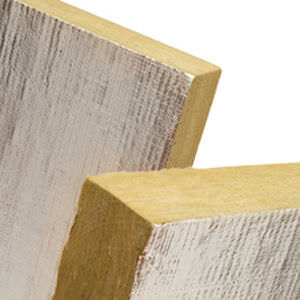
A sheet material such as a Fire Resistance Board, as well as the Vapour Check seen above, is part of contemporary building rules and regulations, as to withstand fire damage for a period of time before allowing it to begin to damage any integral structural elements of a building.
The product that I have researched as for a suitable fire resistant board, is that of | Promat SUPALUX, seen within the image presented, right. Unlike other products that I had explored, the 'SUPALUX' is applicable to both internal partitions, as well as the buildings external envelope, allowing it to be relevant in all spaces of the pavilions technical design.
As well as providing up to 240 minutes worth of fire resistance (in the event of), the Promat product also boasts a vast | | | | The following, is a presentation of the estimate costs involved with the implementation of Promat SUPALUX Fire Resistance Boards within the external wall of the Pavilion.
Boards of 2500mm x 1200mm x 12mm - Sold in sets of 5 at £116.45
13,000 (Wall Length) ÷ 2500 = 5.2 (One Row)
5.2 x 2 = 10.4 Boards for external wall interior
10.4 x £116.45 = £1211.08 (£1211.00)
Total Cost of One External Wall (Interior) Fire Resistance Panels
£1211.00 | | array of specialities within terms of insulation, protections and resistance, most interestingly I found, in having a notable, high impact resistance, in being such a strong material.
Used within construction for approximately thirty years, the Promat SUPALUX is a tried, tested and renowned product that I feel suitable enough to
| retain the atmosphere and environments within the pavilions proposal and design.
With an ease in assembly, both technically and manually in how the boards are attached both by workers and onto the structure, is efficiently ergonomic, leading an exploration into the price of such a valuable product. | |
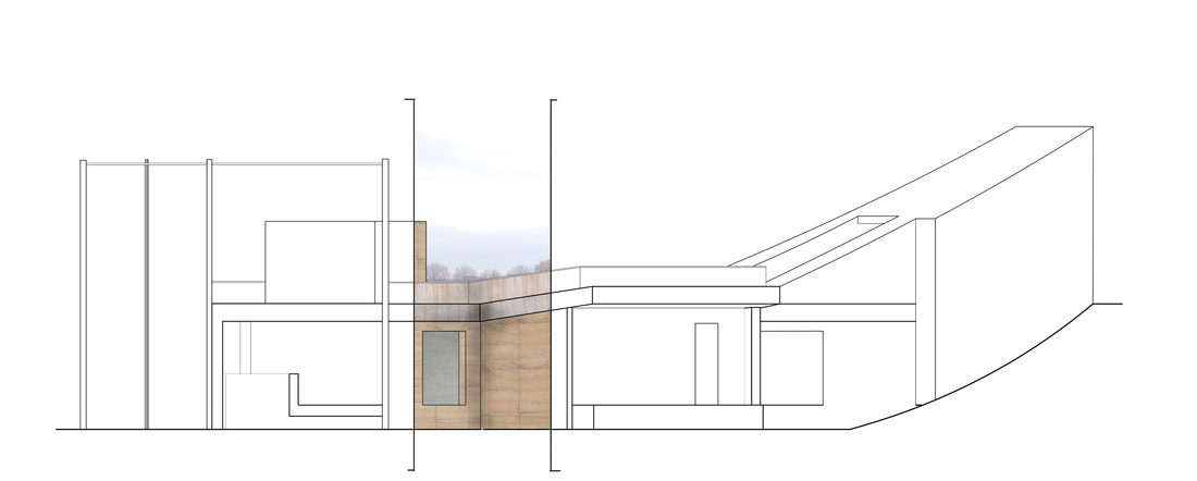
| The image to the right, presents further developments within the producing of a sectional drawing to portray the tectonic build up of the pavilions external wall design.
Unlike that of earlier posts, the external leaf has been elongated as such, to reach ground level in an entirely aesthetic respect, as to avoid the visual impact that an exposed concrete foundation would have upon the design as a whole.
Despite the visual and structural alterations that this scheme has produced - in reference to the steel reaching to the ground as opposed to sitting atop of a concrete base, such as can be seen within the image below - the aspect of the flood | alleviation responsibilities that a structure upon such a site contains, has been retained.
However, within this, there may be some damages to the 'Compressed Earth' blocks or bricks that construct the aesthetic element of the external wall, free of fenestration as to capture the forced visual that can be witnessed from the kitchen space, of the Victoria Embankment Recreation Grounds.
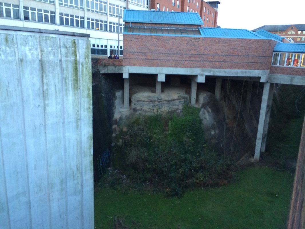
This damage would be in large part, a response to any flooding although, due to the steel skeleton of the structure, will not be compromised in any sense through flooding issues or concerns. | | | | | Although developed, there are several areas that need addressing within the section above, most significantly is the block work of the external leaf and its interface with the steel columns base plate, explained in further detail below. | To the left, is an image of the Victoria Bus Station, Victoria Centre, Nottingham. This was my original proposal of what my structure were to sit above, a piled concrete 'raft' almost, that would elevated whilst retaining visibility underneath as to address the issue of flooding within our proposed site.
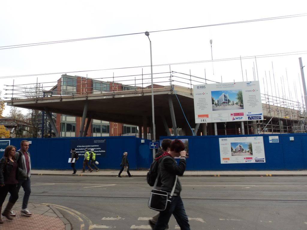
This construction technique has also been implemented within Nottingham Trent University's newly built Student Union building, or 'Byron House', designed by Church Lukas Architects (Seen within the image to the left).
The reason for explaining and exploring this image is to justify what is a rather large or | drastic change to my original pavilion's proposal, in terms of visual quality, a fundamental basis of the Pavilions design, as to appear 'organic' and almost growing from the ground.
Although an effective technique in which to construct, it is visually unappealing, resulting in the concealing of the structure almost. within the cavity of the site that served once as a train station - Nottingham Victoria Station.
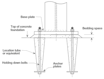
I felt that in altering my design in such a way, can be seen as a positive progression as to avoid aesthetic unpleasantries such as can be seen within the above, and perhaps arguably, the image below also. | | | In order to proceed and progress, I need to explore detailing of the Steel Base plates of columns as well as their interaction and relationships between concrete foundations, of which thus far has proven incredibly difficult without my ability to source such relevant precedents that contain closely similar detail.
I have provided an image of a typical steel base plate of a steel column, expressing its connection with the trench fill foundation concrete that it | sits on top of.
I had been under the impression that - from research into Roy Chudley's 'Construction Technology' - upon sealing a column atop of a concrete foundation, there would then be a layer of concrete applied to the trench, as to encase the column and retain an even ground level.
This would then allow for easier attachment of any cladding system and flooring system as to flesh the structure out. | | Above, is an example of a typical steel base plate that attaches a steel column to a concrete foundation, a technique implemented within my further developed but yet not complete technical section (seen as the first image within this post). |
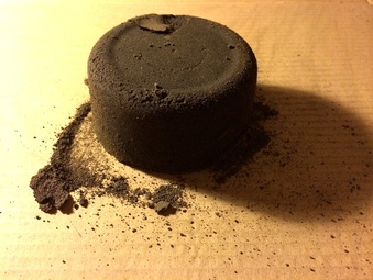
| INITIAL MODEL EXPERIMENT
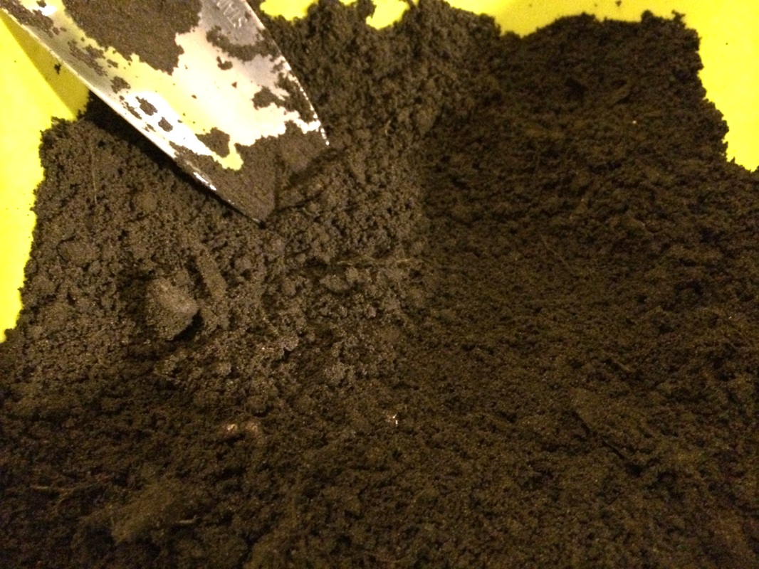
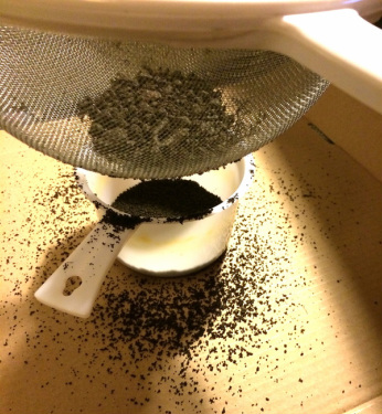
In coordination with the brief, we were expected to carry out three dimensional studies alongside our orthographic presentation of our pavilions tectonic designs. I felt that, as an area that I have faltered within amongst past projects, that I should explore the materiality and texture of the proposed technical solutions, through a form of model making. This also produced an opportunity in which to explore the manual processes of Rammed Earth, therefore providing an interesting basis | on which to produce a 3D study. The following presents the processes upon which were heavily taken from advice from the following website;
http://rammedearth.davis.net.au/ and book; 'Rammed Earth: Design and Construction Guidelines, Peter Walker, BRE Bookshop, 2005. As a starting point, I had collected soil from my current residence, by digging beneath the top layer as to remove significant stone and leaf litter. The earth, according to the website, has to be of a specific moisture content and despite | | In relation to the image above, although I had removed visually obvious vegetation and inorganic materials, some remained within the soil, of which above still retained. The use of a sieve, seen in the images below, allowed for a finer material in which to compact. | | Above, presents the left over fine soils that were later added into the final mixture (within the white microwavable pot seen also, above), as well as an illustration of the sieving process that I had been instructed, through the referred sources in the opening paragraph, to carry out in order to remove any obstructing materials that may effect or harm in any way, the structural build up of these particles of earth. However, some timber elements within larger scale processes are left in throughout these processes for either structural or aesthetic values. | | this being a fairly complicated formula in which to concoct - with the implementation of sands, gravels and cement of particular quantities (%), although there is a 'rule of thumb' solution in which to test its state. This was to take the soil as a handful and if it were to crumble instantly, it was too dry, and if you were to drop it from shoulder height and it were to not break, it was too wet. I carried out this process to find that - to my knowledge - the earth, at this stage, had an appropriate moisture content in which to continue.
REMOVING OF MATERIALS
As seen within the two images, presented to the left, I began to sieve out the inorganic materials, such the plastics and other pieces of litter that I had
| found amongst the soil.
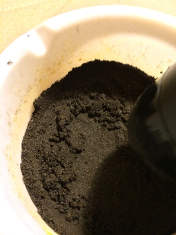
I then began to break down what remained in the sieve, materials of which could fit but had clumped together, and then continued to fill the microwavable pot that I had chosen in which to form the shape of with Rammed Earth. The reasoning behind this, was to create a rounded texture to compliment the proposed, or hopeful, pattern that would be created through the compacting of several layers.
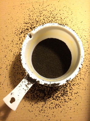
The finer particles of earth that had fallen through the sieve due to their initial size, surrounded the outside of the pot, of which I later, carefully, added to the overall earthy mix, shortly before I began to apply pressure for compacting. | | | The fine finish of this sieving can be seen in the adjacent photograph (right), of which I then had to begin to apply considerable pressure to over the surface area.
The recommended 'Ramming' process, was to apply such pressure that the finished layer was almost 50% less than it had previously been within a free particle state. | This can be seen in the image, left, in which i used to assess the change in heights before and after the addition of soils and their ramming, as to estimate the size of each layer.
The image provided shows a pre-rammed layer of soil within the microwavable pot, as in fact it is an elevational image of that of the image to the right.
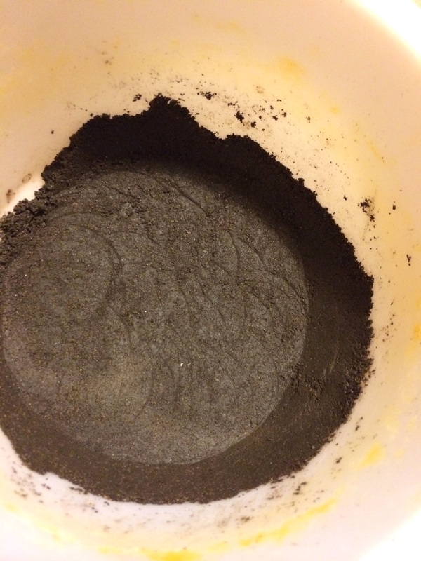
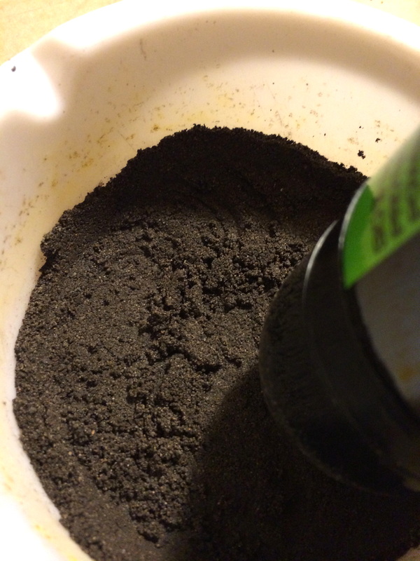
The following process was to then physically ram the material to its desired 50% state, of which I had rather crudely used the end of an empty deodorant can, of which caused the pattern that can be seen within the image below. | | | | Below, presents the markings that were produced through the 'Ramming' of the surface layer of earth within the pot. This was the most difficult and strenuous element of the model making process, as a result of the pressures that were to applied (the time taken explained within the following texts) and the speed in which these were to be carried out within due to loose minerals. The image above, presents the patterns that had been formed within the ramming of the substance, something that is not as noticeable (if there is an occurrence) within larger scale, structural constructions, of which the Rammed Earth is most commonly produced to serve both structural and aesthetic purposes within a design. | | Seen within the two images below, the physical ramming had to be carried out at rather fast speeds, in order to capture all of the loose surface materials that were freed from the build up at the sides of the container. As they sat slightly above the surface of which the pressure was being applied, they fell directly beneath the aerosol can that I had used as a 'rammer' - this was fundamentally a result of the shape of the top of such an object, of which appeared to work fairly effectively.
The results of such can be seen within a pattern formed in the image to the left, which also became an indicator of sorts into when I was to progress to the addition of another layer of earth.
| I felt that in increasing the pace of this aspect of the process, allowed for a more efficient 'compacting' of the soils within the container, the weight of which became increasingly heavily which is obviously expected, but to a surprising degree, as if to express the effects of the effort that was being applied against its surface.
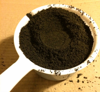
Despite still being moist to touch, the soil had become visibly and physically tougher, to the point where within its container, allowed for little movement, despite my application of lateral pressure through squeezing and still wit the drying process to be carried out. I felt that this was a promising development within the process. | | | | | The image to the left, presents the final layer of lose minerals that was added to the experimental container, before its final ramming and complete product, seen presented through photographic images below.
At this stage, this sample, despite its relatively small size, carried substantial weight within the ramming of the soil towards a compact entity that contained a strength that was non existant within its previous | mineral form or 'state'.
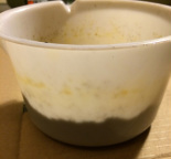
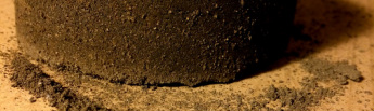
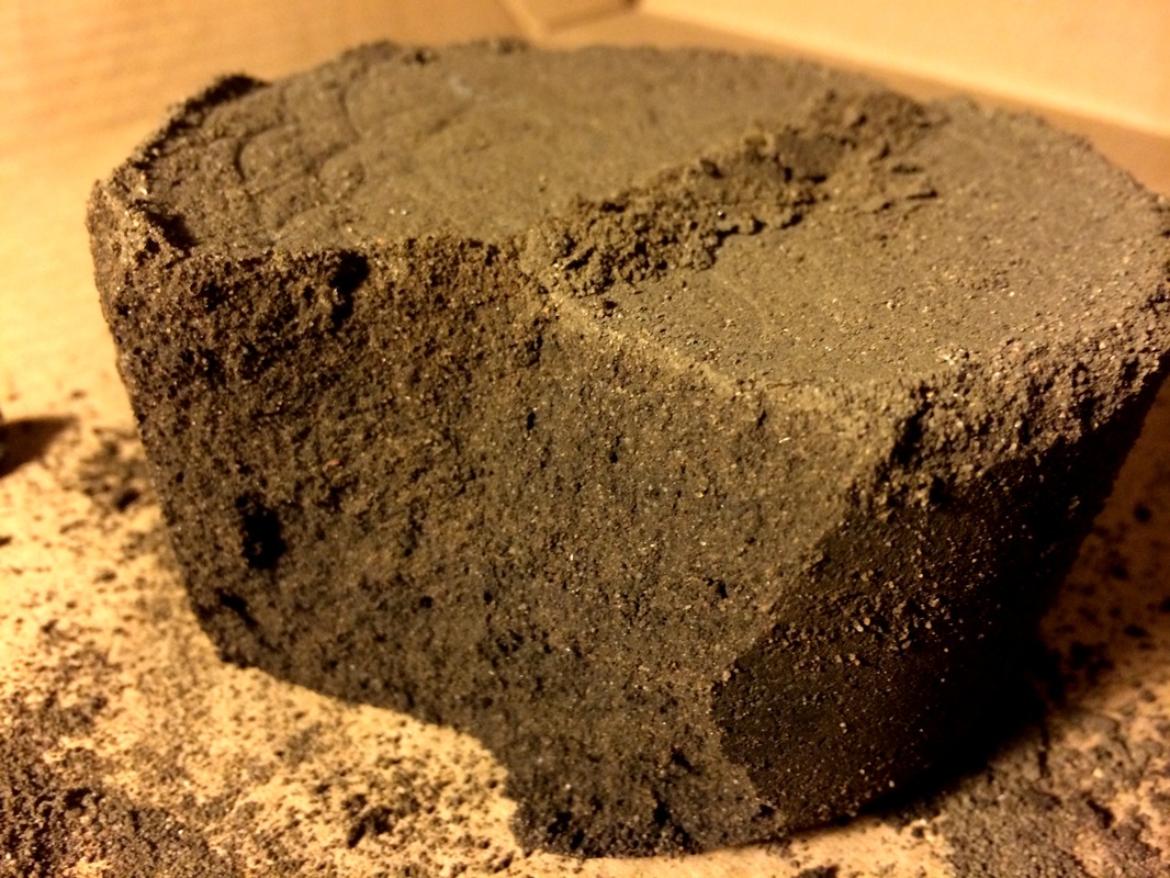
Although this cannot compare to the structural capacities of a 'to scale' rammed earth structure, - despite its expulsion from my design with the opting of earth blockwork, of which this process is particularly applicable to - I feel that this has been a particularly interesting and useful perspective to gain whilst studying rammed earth as a material media, in understanding its physical properties through making. | | | The final model experiment, seen below, despite its overall strength due to the compacting of the soil, does hold the aesthetic that I had hoped, although it can be seen slightly within the image below. | There is a difference in colour within the surface layer to the body of the rest of the experiment, although this appears primarily due to the lack of drying within the base of the form. | | | | Below, presents the resulting damage of a strength experiment that I had attempted, which resulted in the crumbling and exposing of the soils compacted composition, of which the dry to moist areas can be seen separated from each other. | | FURTHER EXPERIMENTS
In order to proceed within exploring a three dimensional study, I feel that I should incorporate this same process although into a different shape or formwork, most specifically, as a brick shape that would be applicable to my tectonic design. I feel that it is also important to produce more than one as to arrange in a block, or brickwork fashion.
Despite the failure of the structural integrity under the pressures that I had applied onto this initial model, I feel that this process of 'construction' | was an efficient and particularly useful study into the physical production and properties of Rammed Earth.
The future production of Compressed Earth bricks presents an opportunity to explore a different formwork, assessing whether this may alter or affect either the physical ramming process, or the drying process and in turn, the final structural properties and integrity of the model. This is most significant however, as to provide direct relevance towards the final tectonic design and presentation of this project. | |
| ORIGINAL RAMMED EARTH PROPOSAL
In response to the previous post, I continued to develop my initial
Rammed Earth wall section drawing, including further detailing into the reinforced, in-situ concrete base and foundations. However, through doing so, as well as further research into the technicalities and tectonics of Green and Garden roofing, I have decided to alter aspects of the structural design, most of which is a shifting. However, as a result of this, I have had to change the emphasis on Rammed Earth as a material quite drastically, in the replacing of the external wall (although not as an entire but partially structural entity), with purely aesthetic blocks, much like that seen on contemporary residential projects, although of a different scale and to a different visual ideal.
This shifting changes very little in the way of the design, although structurally, as presented within the following images, there will be a distinct difference as oppose to the earlier proposals and tectonic design, of which will be concealed.
The steel element will be retained throughout this process, due to cost efficiency, its structural integrity, speed of erection and its recyclable material properties retaining the environmentally sustainable respects and ideals of the structure. However, it will be implemented in an alternate method, more conventionally than that of which was proposed prior to the following developments, in having the rammed earth entirely consuming the steel frame.
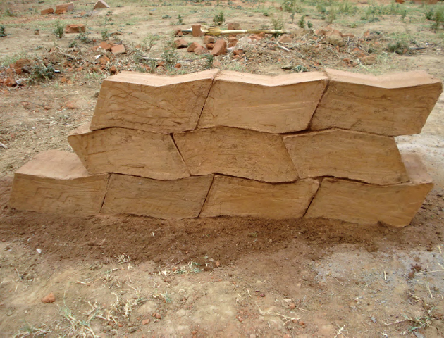
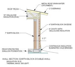
RAMMED EARTH BLOCKWORK
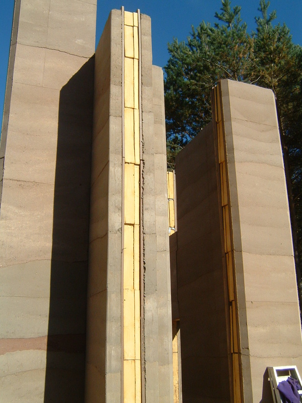
As seen below in the provided image(s), Rammed Earth blocks carry an almost identical aesthetic value, despite their structural capabilities having been largely removed. This also creates an interesting pattern of sorts, across the facades, or selected areas of which this material will be applied - against all external walls in relation to the Pavilion's design.
| | | | | This specific type of block work, is constructed or planned within a similar vein as traditional block work, separated by a cavity of approximately 100mm, and decoration either the internal, the external or perhaps, both leaves of an external wall. In the case of this particular project, unlike in the image provided, the implementation of this material within the design will | become a superficial addition to the structure, as to add an organic texture by physically wearing the site as its skin. I feel that, although it takes away from the natural geological process and aesthetic of traditional Rammed Earth 'structures', there retains that earthy, warm and tactile atmosphere evoked by such a material, harvested potentially still, from the immediate site. | | | The cavity within the structure, in the image to the right, is filled with insulation, as would be necessary within the use of Rammed Earth as the entire envelope. This cavity within my structure also, will contain | insulation, of which can be seen within the original wall proposition above, as well as the revised and developed one below (underneath the precedent sectional image). | The sectional image above, represents closely the photograph to the right, retaining the internal and external Earth Block aesthetic. | | | Although the image above is of the product that the current pricing data is based upon, I feel that their profile is too small in comparison to the aesthetic that I had envisioned and portrayed within my final elevation image, seen below.
However, in finding difficult whilst researching for larger Earth Block elements, I have decided to maintain this current pricing as to gain a footing (at least) of the expenses involved with a material of this nature. | | 'EARTH BLOCKS'
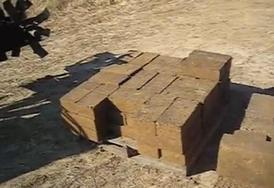
In the use of these 'Earth Blocks', I felt it important to explore existing materials and manufacturers who can provide dimensions, prices and perhaps range in the particular product - a way in which to enhance realism within my research and obtain financial data.
Upon visiting the Open Source Ecology website - a data base of sorts, I discovered that Earth Blocks, although dependant on the companies in which you purchase them from, have an almost universal cost of $1.10 (or £0.67), on a per brick basis. | This is slightly more expensive than that of traditional red bricks, although of a similar size, a result perhaps of the environmental values that Rammed Earth Blocks contain.
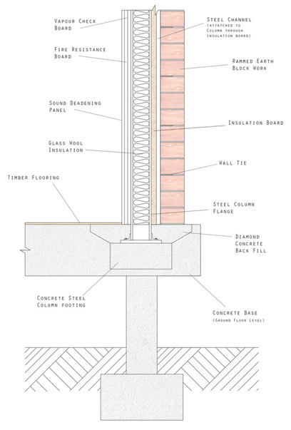
Traditional Brick Prices: from http://www.wickes.co.uk/bricks-blocks+lintels/bricks/icat/bbbricks/However, these 'Earth Blocks' that have been referenced within the adjacent column and image, are of a significantly smaller size than that I had envisioned for the external aesthetic of the Pavilions design, the projection of which can be seen within the elevation graphic provided (below). | | | REVISED EXTERNAL WALL PROPOSAL As oppose to the initial structural rammed earth wall, as well as the then developed 'concealed' steel framed external wall, I then have progressed into the use of Compressed (or rammed earth) block work, retaining aesthetic values and enhancing the structural capabilities of the Pavilion.
This has lead and developed into the envelope that can be seen presented within the image, right, of which a steel column carries the load of the 'Garden Roof' structure, directly above.
Despite its opposition towards elements of my brief perhaps, seen within 'The Pavilion' tab, I feel that this composes a greater cost effectiveness of sorts, in the reduction in uses of materials and machinery in which is required to mix, pour and 'ram' compressed earth walls.
The inclusion of these Rammed Earth blocks, instead creates an aesthetic that I had | desired though my original elevation images, seen above, as well as creating a lighter weight structure in total. This would also act to enhance the speed of the build, as well as perhaps, the application of the interior boards and panels that play their part in affecting the acoustic levels and atmosphere of the internal spaces.
Of these boards, as can be seen within the labelling of the sectional diagram, is the fire resistance, moisture insulation and 'Sound Deadening' panels - of which can be seen within previous posts. These are attached to the steel column members, that would in turn lock in the Glass Wool insulation, situated between the two flanges of the column.
Further insulation is implemented on the external leaf, in a solid board form, through which, a steel channel is attached to the column, in turn providing a surface for the wall ties to protrude from, and support the walls block work element. | | Below, presents my revised external wall section, of which I have appropriately labelled and attempted to represent the material and function of each element through light rendering. I feel that this is an extremely viable structure, in stark contrast to my previous proposal, in presenting a definite development within my personal tectonic understanding of steel frame and block work walls. However, I still feel unsure of issues such as cavities, insulation and most specifically, the concrete base and columns, as well as the steel columns footings within the flooring (of which itself is raised above the ground by 700mm. |
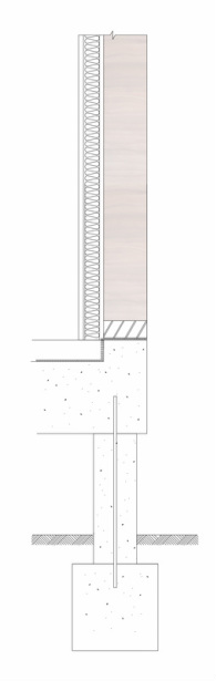
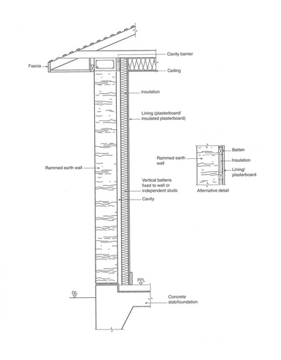
| RAMMED EARTH WALL SECTION
Taken from the extremely informative book 'Rammed Earth: Design and Construction Guidelines', the sectional image of an external Rammed Earth wall seen to the right, presents a basis from which I have been beginning to sketch upon. Through these images, in presenting both the roofing and the floor connections technically (although due to the scale, not in an enormous technical depth of detailing) I have been able to develop an understanding of conventional Rammed Earth structures tectonically. However, seen in my initial sketch below, I am still developing how I can incorporate the steel framed skeleton of the entire Pavilion, into a clear, concise and technically accurate graphic presentation (of which is explained further into this post). Although the scale is not indicated within the image to the right - as well as of the others within the series as part of the book - It does present measurements within the annotation and labelling of the design.
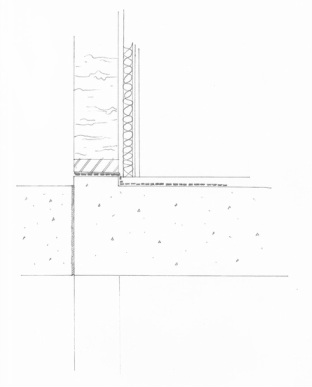
One of the greatest difficulties that I had in producing my initial scaled sketch, seen below (originally drawn at a scale of 1:200) is that of the external Rammed Earth wall's connection within the concrete flooring, that itself does not sit within the ground, but above it due to the flood alleviation scheme that I had incorporated into my design, as a strategic response to the conditions of the site. | The image above is lacking in some detailing graphically, such as can be seen within the addition of a 'alternative detail' in which presents the ways in which these internal surfaces attach to the Rammed Earth wall. Depending upon the scale in which I am to choose for my final graphical presentation on the specified A1 panel, this may be necessary to include separate to the orthographic drawing. | | Even a drawing as inaccurate as that of the one above, has allowed me to assess in greater depth, the complexities of my structural design as well as beginning to think more rationally and technically whilst producing a sectional orthographic such as this. | Within the image to the left, my initial scaled sketch, is similar fundamentally to the image above, although there are few alterations, such as the inclusion of a 'up-stand', located at the base of the wall that separates the damp proof membrane from the Rammed Earth Material. An additional surface has also been added to the plasterboard that sits on the inner leaf of the cavity, as to represent the acoustic insulation panels, or surface, that will dress the walls of the internal kitchen space.
However, relative to my own design, I feel that this is perhaps a way off of the correct tectonic strategy in order to connect a wall of this substance to the concrete 'slab' foundation that sits above an additional level of piles as to create this physical raising of the structure (much like the Farnsworth House, mentioned previously). This is also evident with my failure to include the piled foundation element within this sketch, although revised CAD drawings will be produced with the continued development of the technicalities of this element of my design.
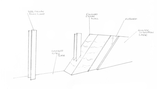
Simultaneous to this, I have began to construct models that present such a material as Rammed Earth, as accurately as possible. Below, is also a development on the graphic presentation of these details as a whole, as well as presenting much clearer my intentions within the realm of steel, and its use as a skeletal frame for the Rammed Earth to be poured around. | | In beginning to explore graphical presentations of the development of my technical design and section, I felt it useful to begin diagramming and sketching (such as can be seen in the image to the right) potential ways/styles of key images for my final A1 panel. I feel that this describes the steel structure well within relation to my final model (see photos in 'The Pavilion' tab) as well as a small and yet informative section of the material build up of the wall. | |
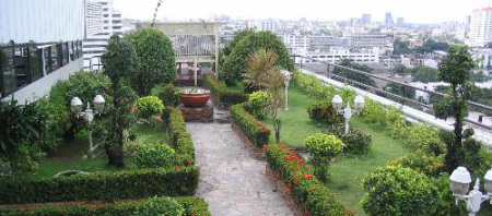
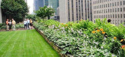
All the information regarding Green Roof requirements is sourced from the following website, http://www.greenroofguide.co.uk/design/, although it has an entire focus upon Green Roofing and not the garden roof that I am beginning to tectonically plan and design within the following posts. However, as Green Roofs must accommodate the weight of the vegetation, soil and perhaps in some cases, the live loads of human maintenance, I felt that this was still relevant and an informative representation of Green Roofing requirements and considerations. | The space above my kitchen, and seen within my final design panels (IDS Design Panels tab) has been developed throughout the project as a Green Roof space, or more specifically a Roof Garden, that due to its purpose of being an outdoor environment, was ideal to provide more facilities and activities within my final Pavilion Design without eating into the maximum heated floor space restriction. The two images to the left, one of which being of one of the several roofs of the 'Rockefeller Center' New York City, provides a clear basic understanding of the visual impact and atmosphere, that I want to create within my Roof Garden space - although this will be in an opening and not entirely wrapped by the context of a city.
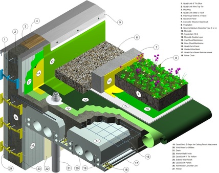
However, due to my use of Rammed Earth, and it being unsuitable structurally to support such a load alone, I will be exploring the connection between a roof and external wall to grasp an understanding of how I can design around this issue, as well as with the use of a steel skeletal framework. This would allow me to then begin to sketch and organise the section of my external wall, to be uploaded at a later date. | | The image to the right, presents a typical tectonic structure that sufficiently sustains a green/garden roof space. Although in terms of materiality (particularly in the use of reinforced concrete for the external wall itself) is is slightly different, this provides the most accurate basis upon which I can draft my own external wall section, roof connection included.
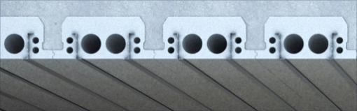
The most interesting aspect that I found within the following image, is that of the roofing structure below, consisting of a largely concrete entity, entitled 'Quad Deck Panel'. | | The information below, on the 'Quad-Deck' panel, is derived from the following website - http://charconcs.com/roofing-solutions/quad-deck-roofing. Although it is a product and therefore is biased towards its characteristics as a constructional material, the reduction in the use of concrete, I feel, sits comfortably within the almost environmentally conscious design that had been integrated within my Pavilion. | QUAD-DECK PANEL
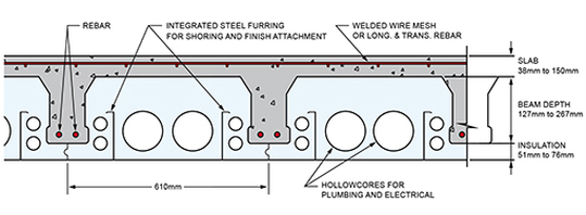
Produced with 40% less concrete that typical reinforced concrete platforms and blocks suited to the supporting of decked roofing, the 'Quad-Deck' panel is a lighter, more efficient and innovative alternative to reinforced concrete.
The image to the left, presents an illustrated and annotated section presenting the features seen above, within the green roof graphic. | | Made of Expanded Polystyrene, each individual panel is attributed with two steel beams, sunken within them as to reinforce the concrete, garden and live loads that it will eventually have to sustain and support. These beams can be seen within both of the images, above and left, as S sections, sitting either side of the hollowcores that penetrate the entire length of the panel (seen and explained within the annotation above). The inclusion of hollowcores, allowing for services (such as 'electrical' and 'plumbing' - see annotation) presents it as an entirely functional and almost competitive alternative to 100% reinforced concrete suspended panels that are commonly used.
The Quad-Deck product, as explained throughout their website, is also, due to its design, an easily assembled component in terms of the duration of time on site. This also has financial repercussions in that less time on site is equal to less man hours and therefore, lesser labour costs, as a result of the 40% less concrete used than that in 100% pre-cast concrete slab roofing. However, depending of the climate and environment of the build, the setting of the concrete and the structure as a whole to allow it to become able to sustain such loads, is around 3-7 days. The 'T' beam concrete sections, completed with reinforcement bars seen within both the above and top right image, are the resulting 60% concrete that remains, significantly reduced to the EPS blocks. These concrete 'T' beams, create a sheer plane in which provides a suitably supported surface for a Green or Garden Roof.
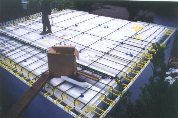
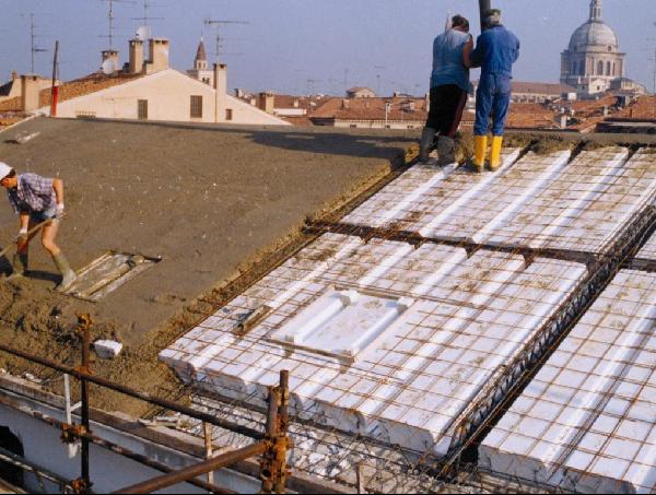
Above, is an image of the EPS block work, being prepared for the addition of 'Rebars' and then the T slabs of concrete. | The image below, presents a more realistic render of how the steel sits within the EPS (Expanded Polystyrene It is this element that creates its almost reinforced concrete like strength. As well as providing sufficient load supporting, reasonable spanning distances (of up to 9.5m) and reducing its 'Floor Mass Dead Load' by up to 50% - a drastically important figure when considering the steel framework that my design consists of, this 'Quad-Deck product also acts as a sufficient thermal and acoustic insulator. In having such low U-Values (of a scale from 0.35-0.17) and providing the required thermal capacity of such a structure, the acoustic insulator feeds well into the atmospheric qualities that the kitchen and dining space below is proposed to possess. |
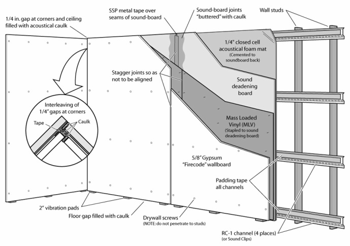
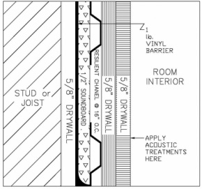
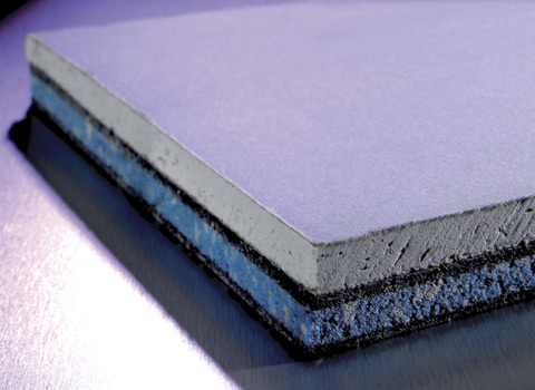
Seen below, is an existing technique, presented through a sourced drawing (http://soundproofing.org/images/wall_2d.jpg), of how a sound controlling wall is constructed and what is consists of in regard to materials and products used. However, this is an exploration into the possibilities of materials to be considered within my own project, as the following examples are to be layered and covered for aesthetic purposes, conflicting greatly with my polarised ideas of using these surfaces as a tactile element of the external wall. The most interesting feature of the image below, is that of the 'Sound Deadening Board', located centrally within the construct of the walls acoustically controlling performance. Seen within the image to the right and the section below, Sound Deadening Boards, or 'Sound Boards', are of a foam substance or material, rendering them rather lightweight and therefore not structurally viable in any sense. However, due to their light nature, these allow for an ease of installation as explored within the following brochure provided from the manufacturer of the JCW Silent Board product, explored in the right hand column. Above, presents a sectional drawing of the acoustic controlling arrangement presented in the image below. Although not representative of the techniques that I had wanted to explore within my own design, this creates an interesting precedent in which to perhaps develop as to reflect the attitudes and ideas that I had outlines within my brief, in regard to the spaces and atmospheres I had wanted to create. This would, I hope, allow for a greater realism within my technical design solutions, in the use or knowledge of current products as well as their composition or integration within similar precedents of design. | http://www.encon.co.uk/sites/default/files/products/images/silent_board_wall_0.jpgJCW SILENT BOARD Far from aesthetic elements, as well as from what would be required within my own construction, I feel that it would be important to explore the potential costing of such precedent products. Although difficult to find a precise price for the product from definitive manufactures and producers, I have found, within the hyperlinks below, that a suitable estimate to calculate from would be approximately £50-60 per panel, which can vary dependent on the size required. The figure provided is for a 27.5mm thick board, named as 'JCW Silent Board', seen within the links provided below. The board in question is 1.2m in both height and length (1.2m x 1.2m), in total 1.44m2 and has a total weight of 24.7kg; a fairly light material in comparison to the other structural elements that comprise conventional external walls. http://www.ebay.co.uk/itm/Wall-Sound-Proofing-Acoustic-Silent-Board-/160703401073Upon these measurements, I can calculate, below the required number of these panels needed as well as the financial costing of this, as to gain a perspective, financially, into this possible technique of creating an acoustically confined space, despite these products being utilised as to deter sound from escaping or bleeding from a space. In my external wall(s) that I am focusing on within this project, I would need approximately two boards, one above the other to obtain the optimal height of the space. | | SOUND DEADENING BOARDS
Soundboards are most commonly used within the construction of a wall, weather it be a partition or an external wall, to combat the sound transmission from one space to another. There are three principles that allow for this sound transmission to be reduced, the foremost being the increasing of the mass of the wall or partition, as to allow a greater distance for the sound to traverse through. This allows the transmission to become longer and with its extended travelling, it becomes weaker through the remaining two principles. These are the 'dampening' and the 'absorbing' of the sound, the latter of which has already been briefly explored within another precedent (see the Restaurant Acoustics Post). This is achieved through the use of materials, in particular the dampening aspect of the process, in restricting the sound waves from vibrating and through the uses of foam like materials and substances. These materials then compose the entire wall through different layers of varied substances, some harder, such as woods (the plywoods and drywalls seen within the provided images) as well as the acoustically orientated 'Sound Deadening Boards' explored in the right hand column. These layers then evoke the function of the absorbing principle, in creating more obstacles for the sound to travel through and become absorbed by before reaching the surrounding space (or atmosphere) that has been protected through these principles. | As a continuation of the calculations started above, my external walls are of 14.5m in length, with an average height of 2.4m (due to the incline that occurs towards the South Easterly space of the structure, an acoustic feature in itself). This would therefore result in the needing of a constant row of two boards being placed above each other over roughly 15m span.
15 ÷ 1.2 = 12.5 (13) One row for the span would be comprised of 13 1.2m x 1.2m boards.
13 x 2 = 26 I would then require a further 13 as to cover the area above the first row of boards, leaving the total for one external wall at 26 boards.
26 x 55 = £1,430 At an average estimated price (in using the
JCW Silent Board, above) of £55.00 I can calculate that the total cost of one external wall of the kitchen space, which would be £1,430.
|
|
 RSS Feed